Engaging questions:
- What renewable energy sources do you know?
- How do solar panels work?
- Where are the solar cells used?
- What will happen when the calculator powered by the solar cell will be closed in the dark place?
- Why do blueberries ripen despite growing in the dark forest?
Equipment and chemicals:
- TiO2 CAS: [13463-67-7]
- HNO3 10-4 mol/dm3 CAS: [7697-37-2]
- methanol CAS: [67-56-1]
- I2 solution in KI in the ethylene glycol (description of the preparation below)
- plates from the conductive glass CAS: [735140-5EA] http://www.sigmaaldrich.com
- fruit (bluberries, cherries, strawberries, etc.) ,
- candle,
- multimeter (voltmeter),
- halogen lamp,
- burner with a tripod,
- adhesive tape,
- a piece of cardboard.
Description of the Activity :
a) Preparation of the I2 solution in KI: 0,127 g of I2 dissolve in 10 cm3 of ethylene glycol, mix, add 0,83 g of KI mixing again. Note! The reagent absorbs moisture. It should be kept in a closed dark bottle, protected by the parafilm.
b) The cell preparation:
The first step is to prepare an emulsion of TiO2:
- In a small beaker mix 1 cm3 of nitric(V) acid solution of a concentration of about 10-4 mol/dm3, pH 3-4 with 3,25 cm3 of ethanol.
- Add 0,75 g of titanium(IV) oxide to the prepared solution, stirring all the time.
- Continue stirring until the suspension appears uniform.
- Having TiO2 suspension ready, a layer of titanium(IV) oxide may be put on the electrode cell.
- The two conductive glass plates (pre-coated with the layer of SnO2) wash with methanol and dry.
- Put the plates next to each other on the cardboard underlay and attach them to it with the use of an adhesive tape (in such way, that only edges of the plate are in contact with the tape). The top plate should be turned to the top from the conductive side, and the bottom one – from the non-conductive. The bottom plate will not be covered; it just helps to cover the top plate.

Figure IV.3. Preparation of the plates for the emulsion distribution.
7. Using a dropper, put several drops of TiO2 emulsion in the straight line along the top edge of the plate.
8. Using a glass rod, spread the suspension of TiO 2 over the top plate. In order to do this, it is recommended to make a few quick moves of the rod up and down.
9. Remove carefully the tape attaching the plates to the cardboard and wash the bottom plate (the one that was not covered) and cover its surface with soot by heating it over the candle.
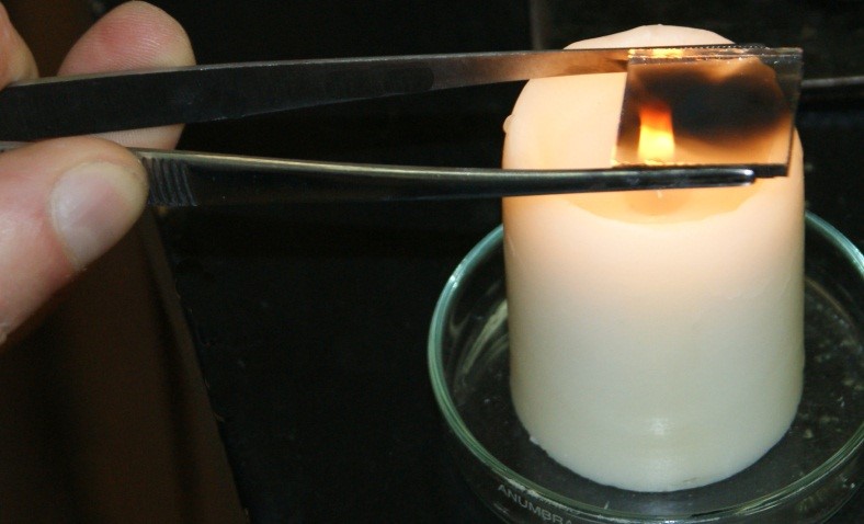
Figure IV.4. Covering the plate with the soot layer.
10. A few minutes after the covering with TiO2, put the plate on a wire gauze with ceramic centre and heat it over the burner flame for about 20 minutes. After that time, wait until the plate cools to room temperature.
11. In a mortar, smash a few strawberries, (or blackberries, cherries, chokeberry) and add about 2 cm3 of water.
12. Put the plate covered with TiO2 in the so-obtained solution (with the TiO2 layer to the bottom) and leave for about 20 minutes.
13. Rinse the plate with water, and then with methanol and leave for drying. The plate should be strongly coloured as a result of the dye adsorption at the surface of the titanium oxide. Such prepared plate is one of the electrodes.
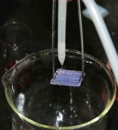
Figure IV.5. Rinsing the plate with methanol.
14. Put the electrode with the adsorbed dye on the flat surface and place from the top, the counter electrode covered with graphite or soot in such way, to enable the contact of plates by the graphite and titanium oxide covered side, with a 4 mm shift between them. The part of the electrode that is has not the titanium(IV) oxide layer, should remain uncovered.
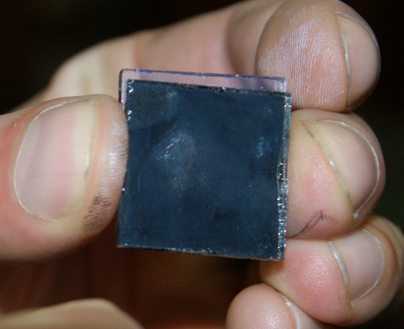
Figure IV.6. Combination of the plates prepared.
15. The plates may be combined with the use of paper clips.
16. Drop an electrolyte between the plates – solution of iodine and potassium iodide in ethylene glycol.
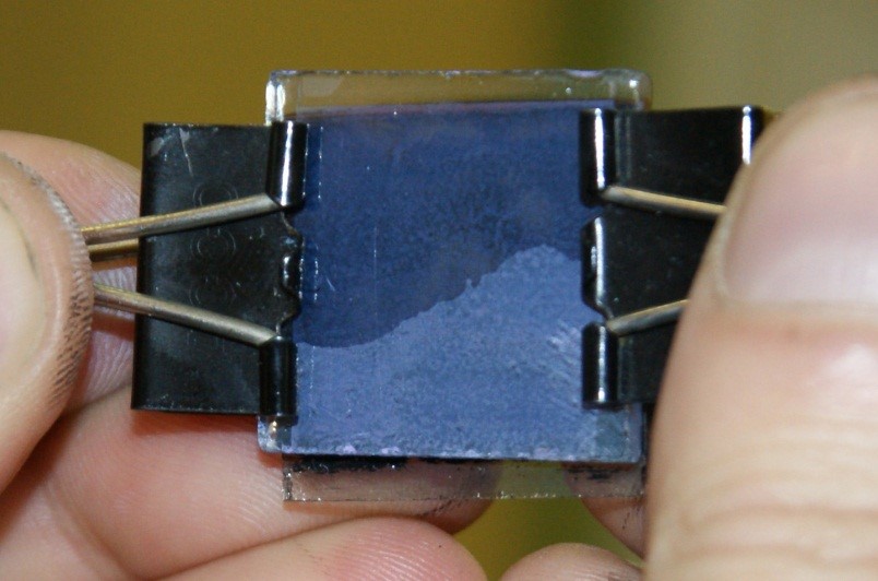
Figure IV.7. The plates combines with the paper clips after dropping an electrolyte.
17. The system prepared in such way, is ready to work.
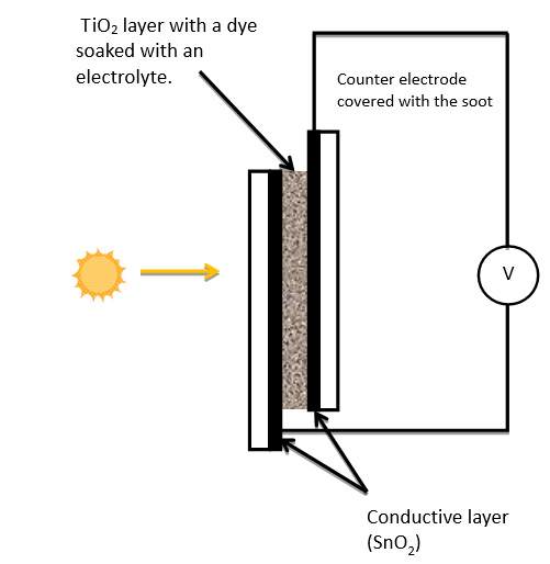
Figure IV.8. A diagram of the solar cell.
18. Connect the multimeter
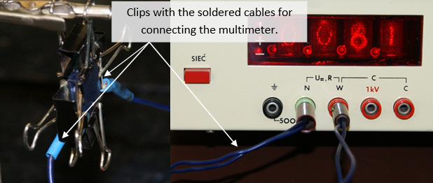
Figure IV.9. An image of the working cell.
19. Illuminate the cell with the halogen lamp and the other types of light (sunlight, torch, laser pointers). Note: You must be careful not to increase the temperature of the cell with the heat emitted by the light sources.
Experiment developed by:
Łukasz Boda, Materiały dydaktyczne: ‘Nanokrystaliczne ogniwo słoneczne’ Uniwersytet Jagielloński
Discussion:
- How does the voltage generated by the cell depend on the type of the light source? Explain, the effect observed.
- How does the voltage generated by the cell depend on the intensity of light?