|
Battery (e.g. 4.5V zinc-carbon, older one with high internal resistance recommended), leads, resistor with adjustable resistance (e.g. 100W), computer, interface and software (e.g. CMA Coach6), current sensor, voltage sensor (if computer with interface is not available, ammeter and voltmeter can be used)
|
|
In this activity students learn about the battery and its properties that influence its use.
Before starting this activity students are already introduced Ohm’s Law, the concept of energy and power dissipated in the resistor. They understand the concept of electromotive force (in terms of work or energy) and internal resistance of the emf device. Firstly they are introduced that the energy produced by the emf device is transferred via resistive dissipation in the external part (load with the total resistance R) and internal part of the circuit (with internal resistance Ri):

Hence the voltage across the external part of the circuit (i.e. the terminal voltage) can be expressed as
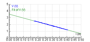
Fig. Experimental results of U related to I
The theoretical background introduction is followed up by four small activities. To carry them out, divide the class into small groups of 2-3 and hand out Classroom Material: Battery and its properties. Each group of students can investigate the behaviour of different battery and finally the results can be compared and discussed within a class discussion.
In order to gain expected results the battery used in the experiment should have quite a large internal resistance (significantly larger than that of the current probe and the connections) so the minimum external resistance can be set to lower value than the battery internal resistance itself. The old already used zinc-carbon 4,5V battery works well since as a result of aging its internal resistance increases significantly with still satisfying value of emf.
In the first activity students explore the behaviour of real battery in a dc circuit measuring the voltage between its terminals in relation to the current through the circuit. Using current and voltage sensor they record the voltage-current relationship and they interpret the diagram. Students learn that the terminal voltage of real emf device is always less than the emf because there is an internal resistance r. Ideal emf device has a zero internal resistance. They understand that the internal resistance of the power source influences its current-carrying capability. The activity is carried out in a guided discovery mode.
In the following two activities they investigate the power transfer from the battery to the load and its efficiency in relation to the load resistance. They carry out guided inquiry in order to discover the condition for the maximum power transfer and maximum efficiency.
The connection with the industry can be stressed by giving examples in which situations the maximum power transfer or maximum power transfer efficiency is used. The efficiency of power transfer from the source to the load increases as the load resistance increases. However, the maximum power transfer is achieved when the load resistance matches the internal resistance of the source, while the efficiency of power transfer is only 50%. The problem of a desire for both high efficiency and maximum power transfer is resolved by a compromise between maximum power transfer and high efficiency. Where the amounts of power involved are large and the efficiency is important, the load resistance is made large relative to the source resistance so that the losses are kept small and high efficiency is achieved in this case (batteries, power supplies, power plants). Where the problem of matching a source to a load is important, as in communications circuits (amplifiers, radio receivers or transmitters), a strong signal may by more important than a high percentage of efficiency. The efficiency in this case is only 50%, however the power transfer would be the maximum which the source is capable to supply.
In the last activity designed as a bounded inquiry in addition to the results gained by measuring students can create simple models on the phenomena investigated experimentally in the previous activities. Based on theoretical knowledge about the processes the students build the models of terminal voltage related to current flowing through the circuit, power transfer and power transfer efficiency related to the load resistance. Hence they compare the model with the experimental data looking for the data that best fit the experimental results.
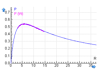

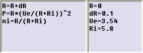
Fig. Model vs. experimental data for a battery (Ue=3,54V, Ri=5,8W)
|